CONVENTIONAL MACHINES
LATHE
A lathe
is a machine tool that
rotates a workpiece about an axis of rotation to perform various operations
such as cutting, sanding, knurling, drilling, deformation, facing, and turning,
with tools that are applied to the workpiece to create an object with symmetry
about that axis.
Lathe machine is one of the most important machine tools which is used in
the metalworking industry. It operates on the principle of a rotating work piece and a fixed cutting tool.
The cutting tool is feed into the work piece which rotates about its own axis
causing the workpiece to form the desired shape.
Types of lathe machine
·
Center
lathe or engine lathe machine
·
Speed
lathe machine
·
Capstan
and turret lathe machine
·
Tool room
lathe machine
·
Bench
lathe machine
·
Automatic lathe
machine
·
Special
lathe machine
· CNC lathe machine
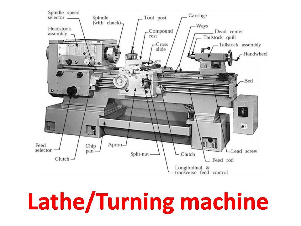
The main parts of the lathe are
Headstock
The headstock is usually located on the left side of the lathe and is equipped
with gears, spindles, chucks, gear speed control levers, and feed controllers.
Tailstock
Usually located on the right side of the lathe, the workpiece is supported at
the end.
Bed
The main parts of the lathe, all parts are bolted to the bed. It includes the
headstock, tailstock, carriage rails and other parts.
Carriage
The carriage is located between the headstock and the tailstock and contains
apron, saddle, compound rest, cross slide and tool post.
Lead Screw
The
lead screw is used to move the carriage automatically during threading.
Feed Rod
It is used to move the carriage from left to right and vice versa.
Chip Pan
It
is present at the bottom of the lathe. Chip pan is used to collect the chips
that are produced during the lathe operation.
Hand Wheel
It
is the wheel that is operated by hand to move a cross slide, carriage,
tailstock and other parts that have handwheel.
MILLING MACHINE
Milling is a process performed with a machine in which the cutters rotate to remove the material from
the work piece present in the direction of the angle with the tool axis. With
the help of the milling machines one can perform many operations and functions
starting from small objects to large ones.
Milling machining is
one of the very common manufacturing processes used in machinery shops and
industries to manufacture high precision products and parts in different shapes
and sizes.
The
milling machines are also known as the multi-tasking machines (MTMs) which are
multi-purpose machines capable of milling and turning the materials as well.
The milling machine has got the cutter installed up on it which helps in
removing the material from the surface of the work piece. When the material
gets cooled down then it is removed from the milling machine.

Main parts of milling machine
Column
& Base
Knee
Saddle and
Swivel Table
Power
Feed Mechanism
Table
Spindle
Over Arm /
Overhanging Arm
Arbor Support.
Milling Process
The
milling machine involves the following processes or phases of cutting:
Surface Finish
Any
material put through the cutting area of the milling machine gets regular
intervals. The side cutters have got regular ridges on them. The distance
between the ridges depends on the feed rate, the diameter of the cutter and the
quantity of cutting surfaces. These can be the significant variations in the
height of the surfaces.
Gang Milling
This
means that more than two milling cutters are involved in a setup like the
horizontal milling. All the cutters perform a uniform operation or it may also
be possible that the cutter may perform distinct operations. This is an
important operation for producing duplicate parts.
Milling Cutters
There
are a lot of cutting tools used in the milling process. The milling cutters
named end mills have special cutting surfaces on their end surfaces so that
they can be placed onto the work piece by drilling. These also have extended
cutting surfaces on each side for the purpose of peripheral milling. The
milling cutters have small cutters at the end corners. The cutters are made
from highly resistant materials that are durable and produce less friction.
Types of Milling Machines
The two main configurations of the milling machining
operations are the types of milling machines. These are the vertical mill and
the horizontal mill. They are further discussed below
Vertical Milling Machines
The vertical mill has a vertically arranged spindle axis
and rotate by staying at the same axis. The spindle can also be extended and
performing functions such as drilling and cutting. Vertical mill has got two
further categories as well: turret mill and bed mill.
The turret mill has got a table that moves
perpendicularly and parallel to the spindle axis in order to cut the material.
The spindle is, however, stationary. Two cutting methods can be performed with
this by moving the knee and by lowering or raising the quill.
The other is the bed mill in which the table moves
perpendicular to the axis of the spindle and the spindle moves parallel to its
axis.
Horizontal Milling Machines
The horizontal mill is also the similar cutter but their
cutters are placed on a horizontal arbor. A lot of horizontal mills have got
rotary tables that help in milling in various angles. These tables are called
the universal tables. Apart from this all the tools that are used in a vertical
mill can also be used in the horizontal mill.