CONVENTIONAL MACHINES

 CONVENTIONAL MACHINES 

LATHE

lathe is a machine tool that rotates a workpiece about an axis of rotation to perform various operations such as cutting, sanding, knurling, drilling, deformation, facing, and turning, with tools that are applied to the workpiece to create an object with symmetry about that axis.

Lathe machine is one of the most important machine tools which is used in the metalworking industry. It operates on the principle of a rotating work piece and a fixed cutting tool. The cutting tool is feed into the work piece which rotates about its own axis causing the workpiece to form the desired shape.

Types of lathe machine

·         Center lathe or engine lathe machine

·         Speed lathe machine

·         Capstan and turret lathe machine

·         Tool room lathe machine

·         Bench lathe machine

·         Automatic lathe machine

·         Special lathe machine

·         CNC lathe machine

The main parts of the lathe are

Headstock
The headstock is usually located on the left side of the lathe and is equipped with gears, spindles, chucks, gear speed control levers, and feed controllers.

Tailstock
Usually located on the right side of the lathe, the workpiece is supported at the end.

Bed
The main parts of the lathe, all parts are bolted to the bed. It includes the headstock, tailstock, carriage rails and other parts.

Carriage
The carriage is located between the headstock and the tailstock and contains apron, saddle, compound rest, cross slide and tool post.

Lead Screw

The lead screw is used to move the carriage automatically during threading.

Feed Rod

It is used to move the carriage from left to right and vice versa.

Chip Pan

It is present at the bottom of the lathe. Chip pan is used to collect the chips that are produced during the lathe operation.

Hand Wheel

It is the wheel that is operated by hand to move a cross slide, carriage, tailstock and other parts that have handwheel.


MILLING MACHINE

Milling is a process performed with a machine in which the cutters rotate to remove the material from the work piece present in the direction of the angle with the tool axis. With the help of the milling machines one can perform many operations and functions starting from small objects to large ones.

Milling machining is one of the very common manufacturing processes used in machinery shops and industries to manufacture high precision products and parts in different shapes and sizes.

The milling machines are also known as the multi-tasking machines (MTMs) which are multi-purpose machines capable of milling and turning the materials as well. The milling machine has got the cutter installed up on it which helps in removing the material from the surface of the work piece. When the material gets cooled down then it is removed from the milling machine.   


Main parts of milling machine

Column & Base

Knee

Saddle and Swivel Table

Power Feed Mechanism

Table

Spindle

Over Arm / Overhanging Arm

Arbor Support.


Milling Process

The milling machine involves the following processes or phases of cutting:

Surface Finish

Any material put through the cutting area of the milling machine gets regular intervals. The side cutters have got regular ridges on them. The distance between the ridges depends on the feed rate, the diameter of the cutter and the quantity of cutting surfaces. These can be the significant variations in the height of the surfaces.

Gang Milling

This means that more than two milling cutters are involved in a setup like the horizontal milling. All the cutters perform a uniform operation or it may also be possible that the cutter may perform distinct operations. This is an important operation for producing duplicate parts.

Milling Cutters

There are a lot of cutting tools used in the milling process. The milling cutters named end mills have special cutting surfaces on their end surfaces so that they can be placed onto the work piece by drilling. These also have extended cutting surfaces on each side for the purpose of peripheral milling. The milling cutters have small cutters at the end corners. The cutters are made from highly resistant materials that are durable and produce less friction.


Types of Milling Machines

The two main configurations of the milling machining operations are the types of milling machines. These are the vertical mill and the horizontal mill. They are further discussed below

Vertical Milling Machines

The vertical mill has a vertically arranged spindle axis and rotate by staying at the same axis. The spindle can also be extended and performing functions such as drilling and cutting. Vertical mill has got two further categories as well: turret mill and bed mill.

The turret mill has got a table that moves perpendicularly and parallel to the spindle axis in order to cut the material. The spindle is, however, stationary. Two cutting methods can be performed with this by moving the knee and by lowering or raising the quill.

The other is the bed mill in which the table moves perpendicular to the axis of the spindle and the spindle moves parallel to its axis.

Horizontal Milling Machines

The horizontal mill is also the similar cutter but their cutters are placed on a horizontal arbor. A lot of horizontal mills have got rotary tables that help in milling in various angles. These tables are called the universal tables. Apart from this all the tools that are used in a vertical mill can also be used in the horizontal mill.


Logic gate

Logic gates are the basic building blocks of any digital system. It is an electronic circuit having one or more than one input and only one output. The relationship between the input and the output is based on certain logic. Based on this, logic gates are named as AND gate, OR gate, NOT gate etc.

There are basically seven types of logic gates, lets discuss about them

1.   NOT Gate

2.   AND Gate

3.   NAND Gate

4.   OR Gate

5.   NOR Gate

6.   X-OR Gate

7.   X-NOR Gate


NOT Gate

A NOT gate provides a low output when the input is high and high output when the input is low. Because of producing an opposite output as compared to input it is also known as an Inverter.


Inverting NOT gates are single input devices which have an output level that is normally at logic level “1” and goes “LOW” to a logic level “0” when its single input is at logic level “1”, in other words it “inverts” (complements) its input signal. The output from a NOT gate only returns “HIGH” again when its input is at logic level “0” giving us the Boolean expression of:  A = Q.


AND Gate


An AND gate is a digital logic gate with two or more inputs and one output that performs logical conjunction. The output of an AND gate is high only when all of the inputs are high. If one or more of an AND gate's inputs are low, then the output of the AND gate will be low.


NAND Gate


In digital electronics, a NAND gate (NOT-AND) is a logic gate which produces an output which is low only if all its inputs are high; thus its output is complement to that of an AND gate. A LOW (0) output results only if all the inputs to the gate are HIGH (1); if any input is LOW (0), the result will be a HIGH (1) output. NAND gate is inverse of AND gate.


OR Gate


An OR gate is a digital logic gate with two or more inputs and one output that performs 
logical disjunction. The output of an OR gate is high when one or more of its inputs are high. If all of an OR gate's inputs are low, then the output of the OR gate is low.


NOR Gate


The NOR gate is a digital logic gate that implements logical NOR operation. A HIGH output (1) results if both the inputs to the gate are LOW (0); if one or both input is HIGH (1), a LOW output (0) is observed. NOR is the result of the negation of the OR operator.


X-OR Gate


XOR gate (sometimes EOR, or EXOR and pronounced as Exclusive OR) is a digital logic gate that gives a true (1 or HIGH) output when the number of true inputs is odd. An XOR gate implements an exclusive or; that is, a true output results if one, and only one, of the inputs to the gate is true. If both inputs are false (0/LOW) or both are true, a false output results. XOR represents the inequality function, i.e., the output is true if the inputs are not alike otherwise the output is false. A way to remember XOR is "must have one or the other but not both".


X-NOR gate


The XNOR gate (sometimes ENOR, EXNOR or NXOR and pronounced as Exclusive NOR) is a digital logic gate whose function is the logical complement of the Exclusive OR (XOR) gate. The two-input version implements logical equality, behaving according to the truth table to the right, and hence the gate is sometimes called an "equivalence gate". A high output (1) results if both of the inputs to the gate are the same. If one but not both inputs are high (1), a low output (0) results.

Belt

belt is a loop of flexible material used to link two or more rotating shafts mechanically. Belts may be used as a source of motion, to transmit power efficiently or to track relative movement. Belts are looped over pulleys and may have a twist between the pulleys, and the shafts need not be parallel.

In a two pulley system, the belt can either drive the pulleys normally in one direction or the belt may be crossed, so that the direction of the driven shaft is reversed. As a source of motion, a conveyor belt is one application where the belt is adapted to carry a load continuously between two points. The belt drive can also be used to change the speed of rotation, either up or down, by using different sized pulleys.


Material used for belt : Leather, rubber, fabric, synthetic polymers

Properties of a belt material

  1. The material from which belt is made of should have high coefficient of friction.
  2. To withstand the tensions created, the belt material should have high tensile strength.
  3. When belt passes through pulley bending stress is induced, to avoid this material should be flexible and should not be rigid.
  4. The material should have water resistance.

 Types of belts

1.   Flat Belt

2.   V-Belt

3.   Round Belt

4.   Timing Belt 

1 Flat belt


Flat belts were widely used in the 19th and early 20th centuries in line shafting to transmit power in factories. They were also used in countless farmingmining, and logging applications, such as bucksawssawmillsthresherssilo blowersconveyors for filling corn cribs or hayloftsbalers,  water pumps and electrical generators. Flat belts are still used today, although not nearly as much as in the line-shaft era. The flat belt is a simple system of power transmission that was well suited for its day. It can deliver high power at high speeds (373 kW at 51 m/s), in cases of wide belts and large pulleys. But these wide-belt-large-pulley drives are bulky, consuming much space while requiring high tension, leading to high loads, and are poorly suited to close-centers applications, so V-belts have mainly replaced flat belts for short-distance power transmission.


Advantages of flat belts

  1. Flat belt can be used where the distance between pulleys are more.
  2. They have high load carrying capacity.
  3. They can be employed where high operating speed is required.
  4. They produce less noise compared to v-belts.
  5. They can absorb shock loads compared to v-belts. 

Disadvantages of flat belts

  1. Due to high load the belt may slip over the pulley.
  2. In long run the belt gets elongated and may slip
  3. High pulley diameter is required. 

2. V-Belt

V belts solved the slippage and alignment problem. It is now the basic belt for power transmission. They provide the best combination of traction, speed of movement, load of the bearings, and long service life. They are generally endless, and their general cross-section shape is roughly trapezoidal (hence the name "V"). The "V" shape of the belt tracks in a mating groove in the pulley (or sheave), with the result that the belt cannot slip off. The belt also tends to wedge into the groove as the load increases the greater the load, the greater the wedging action improving torque transmission and making the V-belt an effective solution, needing less width and tension than flat belts. 


Advantages and Disadvantages of V-belt Drive over Flat Belt Drive:-


Following are the advantages and disadvantages of the V-belt drive over flat belt drive :-


Advantages:-


1. The V-belt drive gives compactness due to the small distance between centers of pulleys.
2. The drive is positive, because the slip between the belt and the pulley groove is negligible.
3. Since the V-belts are made endless and there is no joint trouble, therefore the drive is smooth.
4. It provides longer life, 3 to 5 years.
5. It can be easily installed and removed.
6. The operation of the belt and pulley is quiet.
7. The belts have the ability to cushion the shock when machines are started.
8. The high velocity ratio (maximum 10) may be obtained.
9. The wedging action of the belt in the groove gives high value of limiting *ratio of tensions. Therefore the power transmitted by V-belts is more than flat belts for the same coefficient of friction, arc of contact and allowable tension in the belts.
10. The V-belt may be operated in either direction, with tight side of the belt at the top or bottom. The center line may be horizontal, vertical or inclined.


Disadvantages:-


1. The V-belt drive cannot be used with large center distances, because of larger weight per unit length.
2. The V-belts are not so durable as flat belts.
3. The construction of pulleys for V-belts is more complicated than pulleys of flat belts.
4. Since the V-belts are subjected to certain amount of creep, therefore these are not suitable for constant speed applications such as synchronous machines and timing devices.
5. The belt life is greatly influenced with temperature changes, improper belt tension and mismatching of belt lengths.
6. The centrifugal tension prevents the use of V-belts at speeds below 5 m/s and above 50 m/s.

3. Round belt

Round belts are a circular cross section belt designed to run in a pulley with a 60 degree V-groove. Round grooves are only suitable for idler pulleys that guide the belt, or when O-ring type belts are used. The V-groove transmits torque through a wedging action, thus increasing friction. Nevertheless, round belts are for use in relatively low torque situations only and may be purchased in various lengths or cut to length and joined, either by a staple, a metallic connector, gluing or welding. Early sewing machines utilized a leather belt, joined either by a metal staple or glued, to great effect.

4.Timing belt

Timing belts also known as toothednotchcog, or synchronous belts are a positive transfer belt and can track relative movement. These belts have teeth that fit into a matching toothed pulley. When correctly tension, they have no slippage, run at constant speed, and are often used to transfer direct motion for indexing or timing purposes. They are often used instead of chains or gears, so there is less noise and a lubrication bath is not necessaryCamshafts of automobiles, miniature timing systems, and stepper motors often utilize these belts. Timing belts need the least tension of all belts and are among the most efficient. They can bear up to 200 hp at speeds of 16,000 ft/min (4,900 m/min).
Advantages of Timing belt

1.   Precision registration and timing with no loss of high torque carrying capability.

2.   Minimal vibration.

3.   Positive slip proof engagement.

4.   Wide speed range, especially important when the entire speed range is developed from a single source.

5.   Virtually no elongation (stretching) due to wear.

6.   High mechanical efficiency, as much as 98% when properly maintained. By contrast, chain drives are in the 91-98% efficiency range, while V-Belts average in the 93-98% range.

7.   Power transmission efficiency is not lost with use.

8.   Clean operation, no need for lubrication.

9.   Reduced noise.

10.                Long, dependable trouble-free service.

11.                Excellent abrasion resistance.

12.                Rust resistant.

13.                Resists chemicals and contaminants.

14.                Increased drive design options.

15.                Weight savings.

16.                Safety issues.

17.                Economical operations.

Disadvantages of Timing belt

1.   Relatively high purchase cost

2.   Need for specially fabricated toothed pulleys.

3.   Less protection from overloading, jamming, and vibration due to their continuous tension cords.

4.   Lack of clutch action only possible with friction-drive belts, and the fixed lengths, which do not allow length adjustment unlike link V-belts or chains.

Bearing and Types

BEARING

bearing is a machine element that constrains relative motion to the desired motion, and reduces friction between moving parts. The design of the bearing may, provide for free linear movement of the moving part or for free rotation around a fixed axis or, it may prevent a motion by controlling the vectors of normal forces that bear on the moving parts. Most bearings facilitate the desired motion by minimizing friction.

Types of Bearing

Bearings are classified broadly according to the type of operation, the motions allowed, or to the directions of the loads applied to the parts.


1. ROLLING BEARING

A rolling bearing is a bearing which carries a load by placing rolling elements such as balls or rollers between two bearing rings called races. The relative motion of the races (Outer race and inner race) causes the rolling elements to roll with very little rolling resistance and with little sliding.

Rolling-element bearings have the advantage of a good trade-off between cost, size, weight, carrying capacity, durability, accuracy, friction, and so on.

There are two types of Rolling bearing

(I) Ball Bearing

(II) Roller Bearing

(I) BALL BEARING

ball bearing is a type of rolling-element bearing that uses balls to maintain the separation between the bearing races.

The purpose of a ball bearing is to reduce rotational friction and support radial and axial loads. It achieves this by using at least two races to contain the balls and transmit the loads through the balls. In most applications, one race is stationary and the other is attached to the rotating assembly like a hub or shaft. As one of the bearing races rotates it causes the balls to rotate as well. Because the balls are rolling they have a much lower coefficient of friction than if two flat surfaces were sliding against each other.

Ball bearings tend to have lower load capacity for their size than other kinds of rolling-element bearings due to the smaller contact area between the balls and races. However, they can tolerate some misalignment of the inner and outer races.

There are FOUR types of ball Bearing


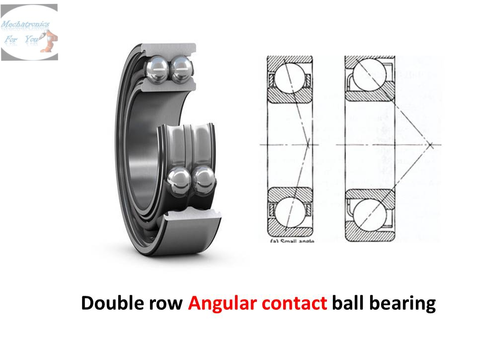
a. Angular contact Ball bearing


An angular contact ball bearing uses axially asymmetric races. An axial load passes in a straight line through the bearing, whereas a radial load takes an oblique path that acts to separate the races axially. So the angle of contact on the inner race is the same as that on the outer race. Angular contact bearings better support combined loads (loading in both the radial and axial directions) and the contact angle of the bearing should be matched to the relative proportions of each. The larger the contact angle (typically in the range 10 to 45 degrees), the higher the axial load supported, but the lower the radial load. In high speed applications, such as turbines, jet engines, and dentistry equipment, the centrifugal forces generated by the balls changes the contact angle at the inner and outer race.


b. Deep groove ball bearing


Deep groove ball bearings are the most widely used bearing type and are particularly versatile. They have low friction and are optimized for low noise and low vibration which enables high rotational speeds. They accommodate radial and axial loads in both directions, are easy to mount, and require less maintenance than other bearing types. 


c. Self aligning ball bearing

Self-aligning ball bearings are constructed with the inner ring and ball assembly contained within an outer ring that has a spherical raceway. This construction allows the bearing to tolerate a small angular misalignment resulting from shaft or housing deflections or improper mounting. The bearing was used mainly in bearing arrangements with very long shafts, such as transmission shafts in textile factories. One drawback of the self-aligning ball bearings is a limited load rating, as the outer raceway has very low osculation.


d. Thrust bearing

Thrust ball bearings, composed of bearing balls supported in a ring, can be used in low thrust applications where there is little axial load.

Thrust bearings absorb axial loads from rotating shafts into the stationary housings or mounts in which they are turning. Axial loads are those transmitted linearly along the shaft. Good examples of axial loads are the forward thrust on boats or prop-driven airplanes as a result of their propeller's rapid rotation.


(II) ROLLER BEARING

Common roller bearings use cylinders of slightly greater length than diameter. Roller bearings typically have higher radial load capacity than ball bearings, but a lower capacity and higher friction under axial loads. If the inner and outer races are misaligned, the bearing capacity often drops quickly compared to either a ball bearing or a spherical roller bearing.

As in all radial bearings, the outer load is continuously re-distributed among the rollers. Often fewer than half of the total number of rollers carry a significant portion of the load. 

There are FOUR types of roller bearing

a. Taper roller bearing

Tapered roller bearings use conical rollers that run on conical races. Most roller bearings only take radial or axial loads, but tapered roller bearings support both radial and axial loads, and generally can carry higher loads than ball bearings due to greater contact area. Tapered roller bearings are used, for example, as the wheel bearings of most wheeled land vehicles. The downsides to this bearing is that due to manufacturing complexities, tapered roller bearings are usually more expensive than ball bearings; and additionally under heavy loads the tapered roller is like a wedge and bearing loads tend to try to eject the roller; the force from the collar which keeps the roller in the bearing adds to bearing friction compared to ball bearings.

b. Spherical roller bearing

Spherical roller bearings have an outer ring with an internal spherical shape. The rollers are thicker in the middle and thinner at the ends. Spherical roller bearings can thus accommodate both static and dynamic misalignment. However, spherical rollers are difficult to produce and thus expensive, and the bearings have higher friction than an ideal cylindrical or tapered roller bearing since there will be a certain amount of sliding between rolling elements and rings.

c. Cylindrical roller bearing

Cylindrical rollers are in linear contact with the raceways. They have a high radial load capacity and are suitable for high speeds.

Some cylindrical roller bearings have no ribs on either the inner or outer ring, so the rings can move axially relative to each other. These can be used as free-end bearings. Cylindrical roller bearings, in which either the inner or outer rings has two ribs and the other ring has one, are capable of taking some axial load in one direction Double-row cylindrical roller bearings have high radial rigidity and are used primarily for precision machine tools.

d. Needle roller bearing

Needle roller bearings use very long and thin cylinders. Often the ends of the rollers taper to points and these are used to keep the rollers captive, or they may be hemispherical and not captive but held by the shaft itself or a similar arrangement. Since the rollers are thin, the outside diameter of the bearing is only slightly larger than the hole in the middle. However, the small-diameter rollers must bend sharply where they contact the races, and thus the bearing fatigues relatively quickly.


2. FLUID BEARING

Fluid bearings are bearings in which the load is supported by a thin layer of rapidly moving pressurized liquid or gas between the bearing surfaces. Since there is no contact between the moving parts, there is no sliding friction, allowing fluid bearings to have lower friction, wear and vibration than many other types of bearings. Thus, it is possible for some fluid bearings to have near-zero wear if operated correctly.

 Fluid bearings are frequently used in high load, high speed or high precision applications where ordinary ball bearings would have short life or cause high noise and vibration. They are also used increasingly to reduce cost. For example, hard disk drive motor fluid bearings are both quieter and cheaper than the ball bearings they replace. Applications are very versatile and may even be used in complex geometries such as lead screw.

They can be broadly classified into two types: hydrostatic bearings and hydrodynamic bearings.

Hydrostatic bearing

Hydrostatic bearings are externally pressurized fluid bearings, where the fluid is usually oil, water or air, and the pressurization is done by a pump.

Hydrodynamic bearing

Hydrodynamic bearings rely on the high speed of the journal (the part of the shaft resting on the fluid) to pressurize the fluid in a wedge between the faces.


3. PLAIN BEARING

A plain bearing, or more commonly sliding bearing and slide bearing in railroading sometimes called a solid bearing, journal bearing, or friction bearing, is the simplest type of bearing, comprising just a bearing surface and no rolling elements. Therefore, the journal (i.e., the part of the shaft in contact with the bearing) slides over the bearing surface. The simplest example of a plain bearing is a shaft rotating in a hole. A simple linear bearing can be a pair of flat surfaces designed to allow motion; e.g., a drawer and the slides it rests on or the ways on the bed of a lathe.

Plain bearings, in general, are the least expensive type of bearing. They are also compact and lightweight, and they have a high load-carrying capacity.


4. MAGNETIC BEARING

A magnetic bearing is a type of bearing that supports a load using magnetic levitation. Magnetic bearings support moving parts without physical contact. For instance, they are able to levitate a rotating shaft and permit relative motion with very low friction and no mechanical wear. Magnetic bearings support the highest speeds of any kind of bearing and have no maximum relative speed.

Active magnetic bearings have several advantages: they do not suffer from wear, have low friction, and can often accommodate irregularities in the mass distribution automatically, allowing rotors to spin around their center of mass with very low vibration.

Passive magnetic bearings use permanent magnets and, therefore, do not require any input power but are difficult to design due to the limitations.

An active magnetic bearing works on the principle of electromagnetic suspension based on the induction of eddy currents in a rotating conductor. When an electrically conducting material is moving in a magnetic field, a current will be generated in the material that counters the change in the magnetic field (known as Lenz's Law). This generates a current that will result in a magnetic field that is oriented opposite to the one from the magnet. The electrically conducting material is thus acting as a magnetic mirror.

The hardware consists of an electromagnet assembly, a set of power amplifiers which supply current to the electromagnets, a controller, and gap sensors with associated electronics to provide the feedback required to control the position of the rotor within the gap. The power amplifier supplies equal bias current to two pairs of electromagnets on opposite sides of a rotor. This constant tug-of-war is mediated by the controller, which offsets the bias current by equal and opposite perturbations of current as the rotor deviates from its center position.


5. JEWEL BEARING

A jewel bearing is a plain bearing in which a metal spindle turns in a jewel-lined pivot hole. The hole is typically shaped like a torus and is slightly larger than the shaft diameter. The jewels are typically made from the mineral corundum, usually either synthetic sapphire or synthetic ruby. Jewel bearings are used in precision instruments where low friction, long life, and dimensional accuracy are important. Their largest use is in mechanical watches.

The advantages of jewel bearings include high accuracy, very small size and weight, low and predictable friction, good temperature stability, and the ability to operate without lubrication and in corrosive environments. They are known for their low kinetic friction and highly consistent static friction.

6. FLEXURE BEARING

A flexure bearing is a category of flexure which is engineered to be compliant in one or more angular degrees of freedom. Flexure bearings are often part of compliant mechanisms. Flexure bearings serve much of the same function as conventional bearings or hinges in applications which require angular compliance. However, flexures require no lubrication and exhibit very low or no friction.

Many flexure bearings are made of a single part: two rigid structures joined by a thin "hinge" area. A hinged door can be created by implementing a flexible element between a door and the door frame, such that the flexible element bends allowing the door to pivot open.

Flexure bearings have the advantage over most other bearings that they are simple and thus inexpensive. They are also often compact, lightweight, have very low friction, and are easier to repair without specialized equipment. Flexure bearings have the disadvantages that the range of motion is limited, and often very limited for bearings that support high loads.


CONVENTIONAL MACHINES

 CONVENTIONAL MACHINES  LATHE A  lathe is a  machine tool  that rotates a workpiece about an axis of rotation to perform various operatio...